Volumetric Light in Deferred Rendering
This post covers the volumetric light system built for a custom DirectX 12 deferred rendering engine. The engine runs an Iris-compatible shader pipeline, and the volumetric light implementation is part of the EnigmaDefault ShaderBundle targeting a Complementary Reimagined visual style.
The system uses shadow map ray marching in the composite pass to produce screen-space light shafts. It integrates with the volumetric cloud system through cloud depth modulation, supports colored underwater light rays through dual shadow map testing, and includes a time-of-day color model with configurable parameters.
Rendering pipeline overview
Volumetric light is calculated in composite1.ps.hlsl after the deferred lighting pass resolves the lit scene and cloud depth. Linear cloud depth from deferred1 feeds into the light shaft shader as an attenuation factor, and the accumulated light is additively blended into the scene before tonemapping.
flowchart TD
    subgraph Deferred["Deferred Pass 1"]
        D1["Deferred Lighting + Atmospheric Fog"]
        D2["Volumetric Clouds"]
        D3["Output colortex5.a\nCloud Linear Depth"]
    end

    subgraph Composite1["Composite Pass 1"]
        C1A["Read vlFactor from colortex5.a"]
        C1B["Underwater Effects"]
        C1C["VL Ray March\nShadow Map Sampling"]
        C1D["Additive Blend\nsceneColor += vl"]
    end

    subgraph Composite5["Composite Pass 5"]
        C5["Tonemapping + Color Grading"]
    end

    D1 --> D2 --> D3
    D3 -.->|"vlFactor"| C1A
    C1A --> C1B --> C1C --> C1D
    Composite1 --> Composite5
Shadow map ray marching
The algorithm casts a ray from the camera toward each screen pixel, stepping through the scene and sampling the shadow map at each position. If a sample is lit (not occluded in the shadow map), it adds to the accumulated volumetric light, which is tinted and blended into the final color.
flowchart LR
    A["Screen Pixel"] --> B["Reconstruct World Position"]
    B --> C["Compute Ray: camera to world pos"]
    C --> D{"Sun Elevation Gate\npassed?"}
    D -->|No| E["Return black"]
    D -->|Yes| F["March along ray"]
    F --> G["Sample shadow map\nat each step"]
    G --> H["Accumulate lit samples"]
    H --> I["Apply color + modulation"]
    I --> J["Additive blend to scene"]
Sun elevation gating
Before ray marching begins, the system checks whether the sun is high enough above the horizon to produce visible light shafts. This avoids shadow map artifacts that appear at grazing angles where depth precision is limited:
float vlTime = saturate((abs(SdotU) - VL_SUN_DEADZONE) / VL_SUN_FADE_RANGE);
if (vlTime <= 0.0)
    return float3(0.0, 0.0, 0.0);
The term SdotU measures the dot product between the sun direction and the up vector. When |SdotU| falls below the deadzone threshold (0.05), volumetric light is disabled. Between the deadzone and the fade boundary (0.05 to 0.25), light intensity scales linearly to full strength, creating smooth transitions during dawn and dusk.
Ray marching loop
Each ray is divided into evenly spaced steps between the camera and the fragment’s world position. Step counts depend on quality level and time of day:
| Quality | Day Samples | Night Samples |
|---|---|---|
| 1 (Low) | 12 | 6 |
| 2 (Medium) | 20 | 10 |
| 3 (High) | 30 | 15 |
| 4 (Ultra) | 50 | 30 |
An Interleaved Gradient Noise dither offsets the starting position per pixel, breaking up banding patterns before temporal anti-aliasing resolves the frame:
float3 rayStep = (rayDir * maxDist) / float(sampleCount);
float3 currentPos = cameraPos + rayStep * dither; // Staggered start

for (int i = 0; i < sampleCount; i++)
{
    float3 shadowUV = WorldToShadowUV(currentPos, shadowView, shadowProj);

    if (IsValidShadowUV(shadowUV))
    {
        float shadow0 = SampleShadowMap(shadowUV, currentPos, ...);
        vlSample = float3(shadow0, shadow0, shadow0);
    }

    // Weight: far samples contribute more than near samples
    float percentComplete = float(i + 1) / float(sampleCount);
    float sampleMult = lerp(percentComplete * 3.0, 1.0, vlSceneIntensity);
    sampleMult /= float(sampleCount);

    volumetricLight += float4(vlSample, 0.0) * sampleMult;
    currentPos += rayStep;
}
Samples are weighted by their position along the ray. Without cloud modulation, distant samples receive up to 3x the weight of nearby samples to emphasize distant light shafts. When cloud modulation is active, weighting becomes uniform. Samples within five world units of the camera are attenuated to prevent pop-in right in front of the view.
Directional modulation
Accumulated light is modulated by two directional factors before coloring:
View-to-light alignment (VdotL): A linear remap (VdotL + 1) * 0.5 concentrates light intensity when looking toward the sun and reduces it when looking away, while keeping shafts visible across wide viewing angles.
Vertical attenuation (VdotU): Looking directly upward scales down volumetric light, avoiding excess brightness against an already bright sky. The attenuation curve blends between full and partial reduction depending on scene intensity.
Time-of-day color transitions
Light shaft color shifts across the day and night cycle based on sunAngle and sunVisibility:
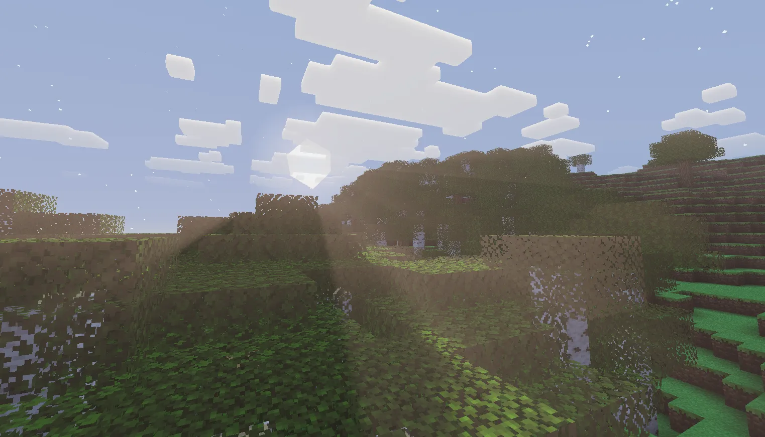
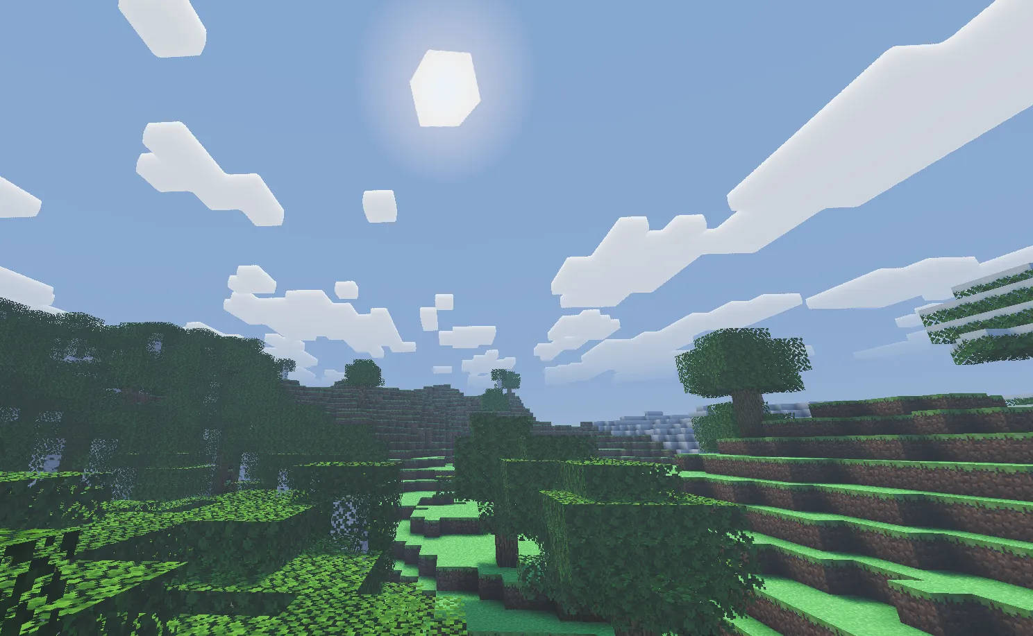
At noon, shafts adopt a cool blue-white tone (VL_NOON_COLOR = float3(0.4, 0.75, 1.3)) matching the sky. Peak noon reduces intensity to 12.5% because uniform ambient sky brightness makes strong shafts look unnatural.
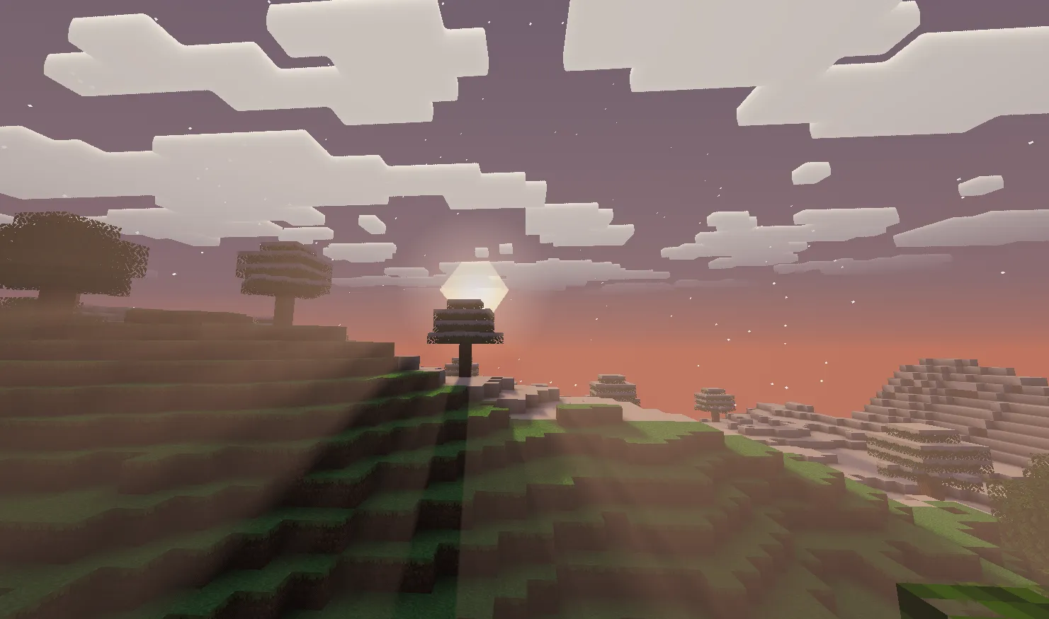
During sunrise and sunset, light shafts shift to warm orange and gold via pow(float3(0.62, 0.39, 0.24), 1.5 + invNoonFactor) scaled by VL_SUNSET_COLOR_MULT (5.5). The power curve enriches warm hues as the sun approaches the horizon, when light shafts are visually prominent.
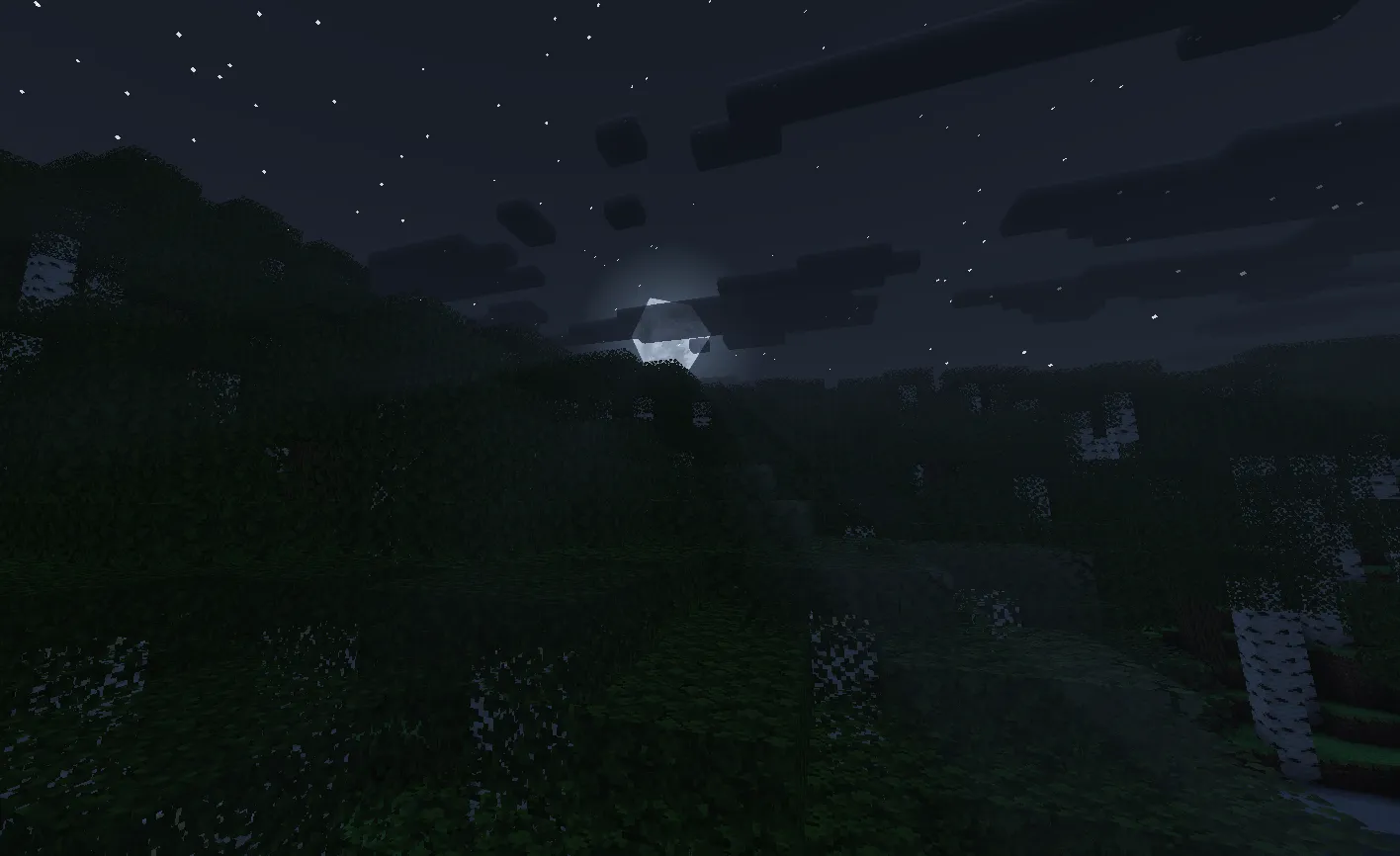
At night, shafts use a faint blue (VL_NIGHT_COLOR = float3(0.05, 0.08, 0.16)) at 15% intensity to produce subtle moonlit rays.
Day and night palettes blend through sunVisibility^2 for smooth twilight transitions:
float3 sunsetVLColor = pow(float3(0.62, 0.39, 0.24),
                           float3(1.5 + invNoonFactor, ...)) * VL_SUNSET_COLOR_MULT;
float3 dayVLColor    = lerp(sunsetVLColor, VL_NOON_COLOR, noonFactor * noonFactor);
float3 vlColor       = lerp(VL_NIGHT_COLOR, dayVLColor, sunVisibility * sunVisibility);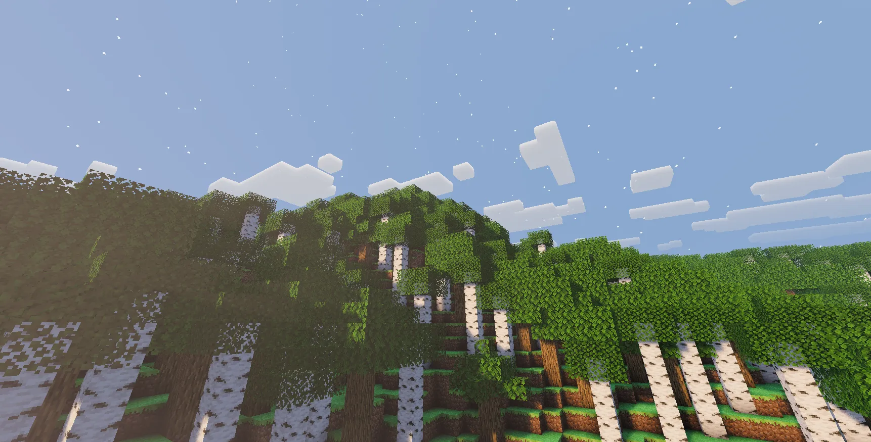
Cloud depth integration
The volumetric cloud system (detailed in the companion cloud post) outputs a linear cloud depth value to colortex5.a during the deferred pass. The composite pass reads this as vlFactor to modulate light shaft intensity.
When vlFactor is 1.0, no cloud occludes the ray and light evaluates at normal strength. When a cloud lies between the camera and the sun, vlFactor drops below 1.0, attenuating the shaft so light does not shine through solid cloud masses:
// deferred1: cloud depth output
cloudLinearDepth = sqrt(lTracePos / renderDistance);
output.color1 = float4(0.0, 0.0, 0.0, cloudLinearDepth);

// composite1: read and apply
float vlFactor = colortex5.Sample(sampler1, input.TexCoord).a;
The cloud system writes depth, and the volumetric light pass reads it. Because the composite pass does not need to re-evaluate cloud density, the passes remain decoupled.
Underwater volumetric light
Submerging the camera switches the shader to an underwater path that simulates colored light rays passing through the water surface:
Dual shadow map testing
Colored underwater rays rely on testing two shadow maps:
shadowtex0stores depth for all geometry including translucent water surfacesshadowtex1stores depth for opaque geometry only
When a ray sample is occluded by shadowtex0 but remains unoccluded in shadowtex1, the light is passing through water. The shader samples shadowcolor1 to obtain the surface’s transmission color:
if (eyeInWater == EYE_IN_WATER)
{
    float shadow0 = SampleShadowForVL(shadowUV, shadowTex0, samp);

    if (shadow0 < 0.5) // Occluded by water surface
    {
        float shadow1 = SampleShadowForVL(shadowUV, shadowTex1, samp);
        if (shadow1 > 0.5) // But NOT by opaque geometry
        {
            // Light passes through water: sample tinted color
            float3 colSample = shadowColTex.Sample(samp, shadowUV.xy).rgb * 4.0;
            colSample *= colSample;  // Square for intensity
            colSample *= vlColorReducer;  // Normalize to prevent double-tinting
            vlSample = colSample;
        }
    }
}
Underwater adaptations
Underwater ray marching adjusts several parameters:
- Maximum march distance is limited to 80 world units, reflecting rapid light loss in water
- Scene intensity is set to 1.0, bypassing cloud attenuation so colored shafts remain visible
- Shadow sampling uses binary comparisons (hard 0 or 1) rather than filtered tests, sharpening shaft boundaries underwater
- Sample weights are scaled by 0.85 to moderate underwater brightness
After marching, underwater attenuation scales the accumulated light using the water fog profile:
float3 underwaterMult = UNDERWATER_MULT_DAY * lerp(UNDERWATER_NIGHT_MULT, 1.0, sunVis2);
float3 uwMult071 = underwaterMult * 0.71;
vl *= uwMult071 * uwMult071; // Squared attenuation
Noise texture
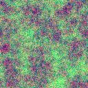
A repeating, bilinear-filtered texture (noise.png) provides supplementary noise patterns that break up regularity in underwater shafts:
Configuration options
All parameters are configured in settings.hlsl using compile-time defines with slider ranges matching the Iris/OptiFine specification.
Core parameters
| Parameter | Default | Range | Purpose |
|---|---|---|---|
LIGHTSHAFT_QUALI | 4 | 1, 2, 3, 4 | Quality level (sample count) |
VL_STRENGTH | 0.5 | 0.25 to 1.5 | Overall VL intensity |
VL_SUNSET_COLOR_MULT | 5.5 | 2.0 to 8.0 | Sunrise/sunset color intensity |
VL_SUN_DEADZONE | 0.05 | 0.05 to 0.25 | Min sun elevation for VL |
VL_SUN_FADE_RANGE | 0.20 | 0.10 to 0.30 | Elevation range for VL ramp |
Underwater parameters
| Parameter | Default | Range | Purpose |
|---|---|---|---|
WATER_VL_STRENGTH | 1.0 | 0.0 to 2.0 | Underwater VL intensity |
WATER_FOG_MULT | 100 | 25 to 300 | Underwater fog density (%) |
WATER_UW_FOG_DISTANCE | 48.0 | 16.0 to 96.0 | Base fog distance in blocks |
UNDERWATER_NIGHT_MULT | 0.6 | 0.3 to 1.0 | Night underwater brightness |
Color constants
// Noon: cool blue-white
VL_NOON_COLOR  = float3(0.4, 0.75, 1.3);

// Night: subtle cool blue
VL_NIGHT_COLOR = float3(0.05, 0.08, 0.16);
VL_NIGHT_MULT  = 0.15;

// Sunset: dynamically computed
// pow(float3(0.62, 0.39, 0.24), 1.5 + invNoonFactor) * VL_SUNSET_COLOR_MULT
Results
Design decisions
Shadow map reuse
The shader samples existing shadow maps (shadowtex0, shadowtex1, shadowcolor1) instead of allocating a separate light volume or running radial blur passes. This avoids additional render targets and passes, within the coverage boundaries of the shadow frustum.
Directional and elevation tuning
The sun elevation cutoff, noon intensity reduction, and view-angle alignment are parameterized to balance atmospheric scattering with visibility. Sunset multipliers are boosted to emphasize horizon shafts, while midday shafts are scaled back to match high-angle sunlight.
Inter-pass communication
The cloud pass writes linear depth to a render target, and the light shaft shader reads it directly. Underwater mode alters ray marching behavior via parameter adjustments rather than branching inside the cloud shader, keeping atmospheric stages decoupled.
Time-based budget allocation
Sample counts and intensities vary with sun position. Sunrise and sunset use full sample counts and warmer palettes where rays are prominent, while midday and night use lower sample counts and reduced brightness.
Looking For More?
Check out some of our other blogs if you haven't already!